EMC optimization of high-speed brushless motor
1. Causes of EMC and protective measures
In high-speed brushless motors, EMC problems are often the focus and difficulty of the whole project, and the optimization process of the whole EMC takes a lot of time. Therefore, we need to correctly recognize the causes for EMC exceeding the standard and the corresponding optimization methods first.
EMC optimization mainly starts from three directions:
Improve the source of interference
In the control of high-speed brushless motors, the most important source of interference is the drive circuit composed of switching devices such as MOS and IGBT. Without affecting the performance of the high-speed motor, reducing the MCU carrier frequency, reducing the switching speed of the switching tube, and selecting the switching tube with appropriate parameters can effectively reduce EMC interference.
Reducing the coupling path of the interference source
Optimizing PCBA routing and layout can effectively improve EMC, and coupling of lines to each other will cause greater interference. Especially for high-frequency signal lines, try to avoid the traces forming loops and the traces forming antennas. If necessary can increase the shielding layer to reduce the coupling.
Means of blocking interference
The most commonly used in EMC improvement is various types of inductances and capacitors, and suitable parameters are selected for different interferences. Y capacitor and common mode inductance are for common mode interference, and X capacitor is for differential mode interference. The inductance magnetic ring is also divided into a high frequency magnetic ring and a low frequency magnetic ring, and two kinds of inductances need to be added at the same time when necessary.
2. EMC optimization case
In the EMC optimization of a 100,000-rpm brushless motor of our company, here are some key points that I hope will be helpful to everyone.
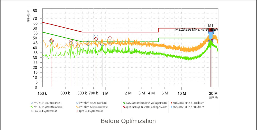
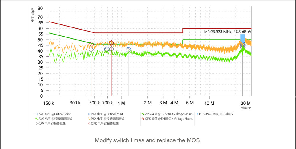
In order to make the motor reach a high speed of one hundred thousand revolutions, the initial carrier frequency is set to 40KHZ, which is twice as high as other motors. In this case, other optimization methods have not been able to effectively improve EMC. The frequency is reduced to 30KHZ and the number of MOS switching times is reduced by 1/3 before there is a significant improvement. At the same time, it was found that the Trr (reverse recovery time) of the reverse diode of the MOS has an impact on EMC, and a MOS with a faster reverse recovery time was selected. The test data is as shown in the figure below. The margin of 500KHZ~1MHZ has increased by about 3dB and the spike waveform has been flattened:
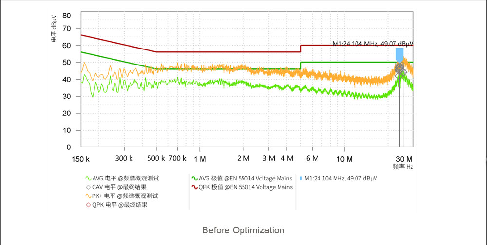
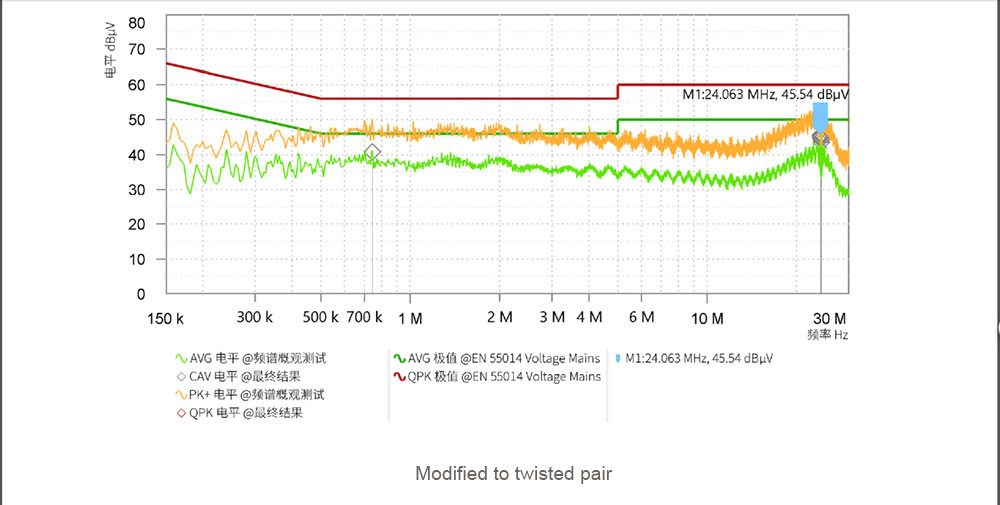
Due to the special layout of the PCBA, there are two high-voltage power lines that need to be bundled with other signal lines. After the high-voltage line is changed to a twisted pair, the mutual interference between the leads is much smaller. The test data is as shown in the figure below, and the 24MHZ margin has increased by about 3dB:
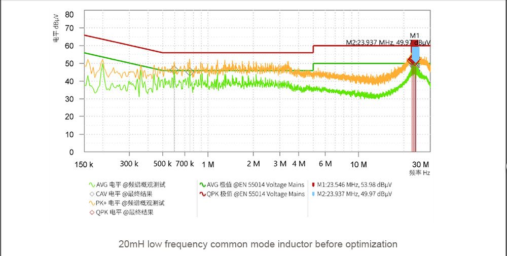
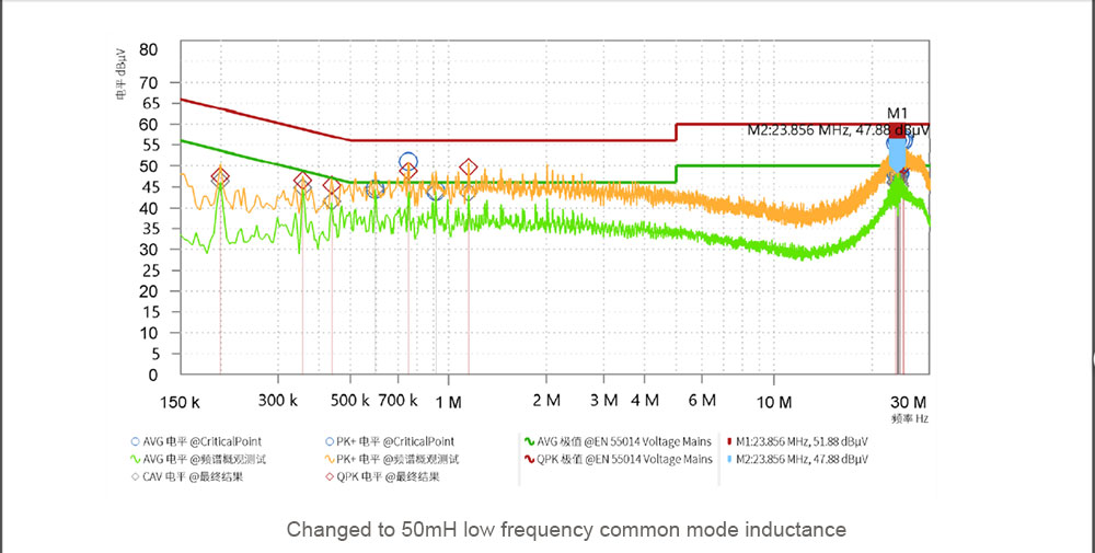
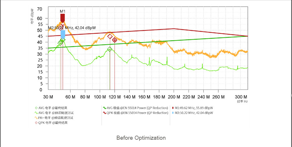
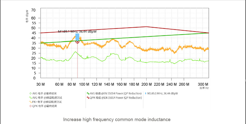
In this case, two common-mode inductors are used, one of which is a low-frequency magnetic ring, with an inductance of about 50mH, which significantly improves EMC in the range of 500KHZ~2MHZ. The other is a high-frequency magnetic ring, with an inductance of about 60uH, which significantly improves EMC in the range of 30MHZ~50MHZ.
The test data of the low-frequency magnetic ring is shown in the figure below, and the overall margin is increased by 2dB in the range of 300KHZ~30MHZ:
The test data of the high-frequency magnetic ring is shown in the figure below, and the margin is increased by more than 10dB:
I hope everyone can exchange opinions and brainstorm on EMC optimization, and find the best solution in continuous testing.
